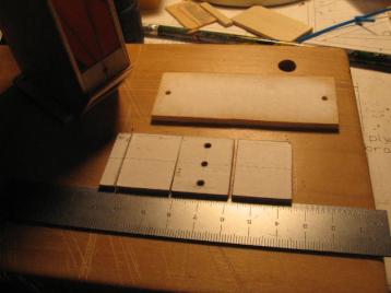
03-23-14: This shows the hatch, one piece of 1/8" balsa, and the top,
made from four pieces. The four pieces of the top are, from left
to right, 1/8" ply, 1/8" balsa, 1/8" ply, and 1/8" balsa.
All of these pieces show computer paper bonded (with 3M General Purpose
45 spray adehesive) to the top side. I experimented with this new
way (new to me) of building. I made plans for all the parts on my
computer. (I used free software called Xfig on a Slackware Linux
based computer.) When I had parts to cut or drill I printed the
plan and glued it to the wood with the spray adhesive. Then I
drilled on the marked centers or I cut beyond the marked edge, then
sanded down to the edge. This helped, but I still found I had to
use great care when drilling holes or shaping a part. It helped
to make an indentation with a center punch before drilling a
hole. And I went slowly when shaping a part. It helped to
use calipers to check the dimensions periodically when sanding down to
a line.
The top was a nasty part to sand. Assembling it from the four
pieces was easy enough, but sanding the edges round, after it was glued
to the top of the pod assembly, was difficult. The alternating
hard and soft of the plywood and balsa was hard to sand to a uniform
shape. If I build another one of these I may make some changes to
avoid this problem.
I should explain that I bought a new tool, a Two-speed Dremel motor
tool and a Dremel drill press.& The two work together and are in some
of the pictures of this collage. They worked well with this new
way of building. I made much use these attachements:
- various drill bits
- cylinderical sanders--good for shaping
- a cutter that looks a little like a drill bit, but cuts on its
side--good for rough cutting
- the cut off wheel--good for cutting the bolts that mount the
pod
By the way, the computer paper sanded off more readily if moistened it
a bit. I do recommend removing the paper, though.
I need to explain the three holes in the top. Originally I
planned to run a wire tie through two of the holes and around the motor
to brace it against the top. The third hole was to help position
a pad that the motor would rest against. As I was building I
decided that the strap and pad were not needed, so I kept the holes for
extra ventillation.
|